
Parts of a Centrifugal Fan: Components and Their Functions

The main parts of a centrifugal fan are the impeller, volute casing, inlet cone, discharge outlet, shaft, bearings, and the motor with its drive. Air enters the impeller along the shaft. The spinning blades throw it outward, and the casing collects it and builds pressure at the outlet.
Large industrial fans also have an inlet box and a shaft seal. Each part affects airflow, pressure, noise and service life. This guide explains what every part does, which part usually causes which fault, and what to check before you buy.
Part | What it does | What to check |
Impeller (fan wheel) | Spins and pushes air outward, adding energy | Blade wear, dust build-up, balance |
Volute casing | Collects air and turns speed into static pressure | Leaks, corrosion, cut-off gap |
Inlet box (large fans) | Turns incoming gas into the impeller eye | Leaks, wear, dust build-up |
Inlet cone | Guides air smoothly into the impeller | Gap with the impeller shroud |
Discharge outlet | Sends air into the duct | Flange fit, flexible connection |
Shaft | Carries torque from the drive to the impeller | Straightness, corrosion near seals |
Shaft seal | Limits gas leaking out or air leaking in at the shaft | Leaks, wear, dust near the bearing |
Bearings and plummer blocks | Support the shaft and hold it in position | Temperature, vibration, grease |
Motor and drive | Supplies power and sets fan speed | Belt tension, coupling alignment |
Base frame | Keeps all parts in line | Loose bolts, grouting |
Dampers and accessories | Control flow and protect people | Free movement, guards in place |
Key Takeaways
- The impeller adds energy to the air. The volute casing turns that air speed into static pressure.
- Blade shape decides pressure, efficiency and how well the fan copes with dust.
- Most vibration traces back to the impeller (dirt, wear, imbalance) or to bearings and alignment.
- SISW fans suit ducted, dusty or higher-pressure duties. DWDI fans move more air for the same impeller diameter.
- Set maintenance by condition (dust, heat, vibration trend), not by a fixed calendar.
How Does a Centrifugal Fan Work?
A centrifugal fan draws air in along its shaft, into the centre (eye) of the impeller. The rotating blades push the air outward, raising its speed and pressure. The volute casing collects this fast-moving air, slows it down, and turns much of its speed into static pressure before it leaves the outlet.
Because air enters along the shaft and leaves from the rim of the impeller, it changes direction by 90 degrees. The scroll-shaped casing widens towards the outlet, so all the air gathers at one discharge opening.
Practical tip: Avoid a sharp duct bend right at the fan inlet. Uneven air entering the impeller eye cuts airflow and pressure, even when every part of the fan is in good shape.
Labelled Diagram of Centrifugal Fan Parts
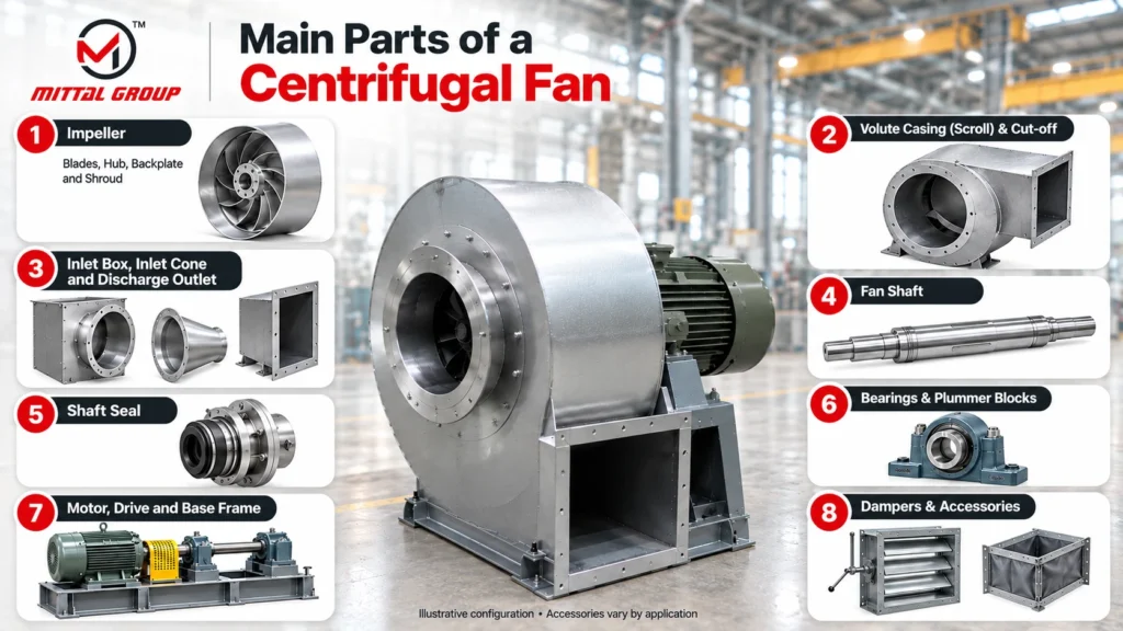
- Inlet cone (bell mouth)
- Impeller shroud (front ring)
- Impeller blades
- Backplate
- Hub
- Volute casing (scroll)
- Cut-off (tongue) and discharge outlet
- Shaft
- Shaft seal
- Bearings in plummer blocks
- Motor, drive and base frame
Practical tip: When you ask for a quote, also ask for the general arrangement (GA) drawing with parts labelled. It makes ordering spares much easier years later.
Main Parts of a Centrifugal Fan and What Each One Does
Below is each part in the order air and power move through the fan.
Impeller: Blades, Hub, Backplate and Shroud
The impeller, also called the fan wheel, is the only part that does work on the air. It has four sections:
- Blades: push the air outward. Their shape sets pressure, efficiency and dust handling.
- Hub: fixes the impeller to the shaft, usually with a key and locking arrangement.
- Backplate: the solid disc the blades are welded to. It transmits torque from the hub to the blades.
- Shroud: the front ring that ties the blade tips together on the inlet side and guides air in.
Some radial impellers for material handling run without a shroud, so solids pass through more easily.
Impeller material depends on gas temperature, chemistry and dust. Mittal Blowers builds fans in mild/carbon steel, stainless steel and alloy steel. The centrifugal blower material guide and the high-temperature fan materials guide explain the choice in detail.
Upgrading only the casing material rarely solves a wear or corrosion problem. The impeller usually wears and corrodes faster than the casing, because it meets the air at much higher speed.
Volute Casing, Scroll and Cut-off
The volute casing is the spiral housing around the impeller. The gap between the impeller and the casing wall grows steadily towards the outlet. This lets the casing collect air from the whole impeller rim and convert its speed (dynamic pressure) into static pressure.
The cut-off, or tongue, is where the scroll meets the outlet. It stops air from circling back around the casing. Its distance from the impeller affects both noise and efficiency.
Large fans often have a split casing, so the impeller can be lifted out without removing all the ducting. On dusty duties, an inspection door and a drain on the casing let you check and clean the impeller without opening the ducts.
Inlet Box, Inlet Cone and Discharge Outlet
Many large industrial fans, such as ID and FD fans, take gas in through an inlet box. This is a chamber bolted to the fan inlet that turns gas arriving from the side or from below into the impeller eye. It saves a sharp duct bend at the inlet. Where the shaft passes through the inlet box, it needs its own seal.
The inlet cone, or bell mouth, guides air smoothly into the impeller eye. The gap or overlap between the cone and the impeller shroud matters. Too large a gap lets air leak back from the high-pressure side, cutting efficiency. Too small a gap can cause rubbing.
The discharge outlet is the flanged opening that connects to the duct. Its position (top horizontal, bottom horizontal, up blast and so on) is fixed by how the casing is built.
Practical tip: Confirm the discharge position and the direction of rotation, seen from the drive side, before you place the order. Changing them later is costly.
Fan Shaft
The shaft carries torque from the motor to the impeller. It must be stiff enough to run well below its critical speed, where vibration rises sharply. On corrosive duties, the shaft is either stainless steel or mild steel with a protective sleeve where it passes through the casing.
On hot-gas fans, a heat slinger or cooling arrangement keeps heat away from the bearings.
Mistake to avoid: Changing the pulley ratio to raise fan speed without asking the maker. The shaft, impeller and bearings are designed for a speed limit, and the power needed rises steeply with speed.
Shaft Seal
Where the shaft passes through the casing, a shaft seal limits gas leaking out or air leaking in. Options range from a simple felt or rope gland to labyrinth and gas-purged seals. A clean-air fan can use a basic seal. A fan on hot, toxic or flammable gas needs a tighter one, so state the gas details clearly in your enquiry.
A worn seal shows up as dust or gas leaking around the shaft, or as dirt reaching the nearest bearing.
Bearings and Plummer Blocks
Most coupling and belt-driven industrial fans use two bearings housed in plummer blocks, mounted on a bearing pedestal. One bearing is fixed to locate the shaft. The other is free, so the shaft can grow with heat without loading the bearings.
Bearings are your early warning system. A rise in bearing temperature or vibration often shows up before any drop in fan performance. Too much grease makes bearings run hot, so follow the quantity and interval in the fan manual rather than greasing by habit.
Motor, Drive and Base Frame
The motor turns the fan through one of three common drive types:
Drive type | How it works | Good for | Watch out for |
Direct drive | Impeller mounted on the motor shaft | Compact, smaller fans, fewer parts | Speed fixed by the motor unless you use a VFD |
Coupling drive | Fan shaft joined to motor by a flexible coupling | Larger fans, hot gas, continuous duty | Needs accurate alignment |
Belt drive | V-belts and pulleys link motor and fan | Easy speed change by swapping pulleys | Belt tension, wear and slip |
On coupling-driven fans, the flexible coupling is a part in its own right. It takes up small misalignment, and its rubber or polymer element wears with time, so keep a spare element in stock.
The base frame holds the motor, bearing pedestal and casing in line. A motor stool raises the motor to the correct height. These parts usually stay in coated mild steel even when wetted parts are stainless. Re-check alignment after the foundation bolts are tightened and grouted on site, because transport and grouting can shift parts that were aligned at the factory.
Dampers and Accessories
Accessories are not part of the fan’s core, but they affect how well it runs:
- Inlet or outlet dampers: control airflow. A VFD is another way to control flow.
- Inlet vane control: pre-swirls air at the inlet to reduce flow and power.
- Flexible connections and anti-vibration mounts: stop vibration passing into ducts and floors.
- Guards, inlet screens and silencers: protect people and reduce noise.
Belt guards, coupling guards and inlet screens are safety items, not optional extras.
If you are planning a new fan or replacing parts on an existing one, the Mittal Blowers team can help you match impeller type, material and drive to your duty. Browse the centrifugal fans and blowers range, or share your airflow, pressure and gas details through the contact page.
Which Impeller Blade Type Suits Your Application?
Choose the blade type by what the air carries and how much pressure you need. Backward-curved blades suit clean or lightly dusty air where efficiency matters. Radial blades suit heavy dust and conveyed material. Forward-curved blades suit low-pressure, high-volume HVAC duty. Airfoil blades give the best efficiency but need clean air.
Blade type | Pressure | Efficiency | Dust handling | Typical use |
Forward-curved | Low | Moderate | Poor, dust sticks to the many small blades | AHUs, HVAC, compact ventilation |
Backward-curved | Medium to high | High | Moderate | Industrial ventilation, process air, boiler draft |
Radial | Medium to high | Lower | Very good, less build-up on blades | Dust-laden gas, material conveying |
Airfoil | Medium to high | Highest | Poor, hollow blades can erode | Clean air, large air handling duties |
Forward-curved fans draw more power as airflow rises, so the motor can overload if the system has less resistance than designed. Backward-curved and airfoil fans are non-overloading: their power peaks and then falls.
Mistake to avoid: Choosing airfoil blades for dusty gas to save power. Erosion and imbalance soon cancel out the energy savings.
SISW vs DWDI: How Inlet Arrangement Changes the Fan
A SISW (single inlet, single width) fan takes air from one side. It suits ducted systems, dusty gas and higher pressures, and it is simple to connect.
A DWDI (double width, double inlet) fan, also called DIDW, has a wider impeller that draws air from both sides. It moves more air for the same impeller diameter and speed. It is common in large ventilation and air handling systems.
A DWDI fan needs clear space on both inlet sides. A wall or duct bend too close to one inlet starves that side and unbalances the airflow. The Mittal Blowers centrifugal DWDI fan page and the article on key applications of DWDI fans show where each type fits.
Centrifugal Fan Parts Checklist for Buyers
Use this list before you send an enquiry or compare quotes:
- Duty point: airflow (CMH) and static pressure at actual site conditions.
- Gas details: temperature, moisture, chemicals and dust load.
- Impeller type: forward, backward, radial or airfoil, matched to the gas.
- Materials: impeller and casing material, plus any coating, lining or wear liners.
- Arrangement: SISW or DWDI, inlet box if needed, discharge position and direction of rotation.
- Drive: direct, coupling or belt; motor rating and enclosure; VFD or damper control.
- Shaft seal: seal type suited to the gas temperature and how harmful a leak would be.
- Bearings: type, lubrication, and mounting points for vibration and temperature sensors.
- Balancing: method used, balance grade and a test report.
- Access: inspection door, drain and split casing where needed.
- Accessories: dampers, guards, flexible connections, anti-vibration mounts.
- Spares: bearings, belts, coupling element, seal and lead times. For critical fans, consider a
spare impeller or rotor.
Practical tip: Share real gas temperature and dust details, not just “normal air”. Many wrong-material failures start with a vague enquiry. The Mittal Blowers low and high pressure blower buyer’s guide covers sizing questions in more depth.
Which Part Causes Which Fan Problem?
Symptom | Likely part | Common causes | First check |
High vibration | Impeller, bearings, base | Dust build-up, erosion, imbalance, misalignment, loose bolts | Clean impeller, check bolts and alignment |
Bearing running hot | Bearings | Too much or too little grease, misalignment, tight belts | Grease quantity, alignment, belt tension |
Rubbing or unusual noise | Inlet cone, impeller, bearings | Impeller touching the cone, loose parts, damaged bearing | Inlet cone gap, listen at each bearing |
Low airflow | Impeller, dampers, belts, inlet | Wrong rotation, belt slip, damper partly shut, choked impeller | Rotation, damper position, belts |
Low pressure | Impeller, casing, inlet cone | Worn blades, large cone gap, casing leaks | Blade condition and cone gap |
Gas or dust leaking at the shaft | Shaft seal | Worn seal, wrong seal type for the gas | Seal condition, shaft straightness |
Motor tripping | Impeller, system | Lower system resistance than designed, cold dense gas at start-up, wrong pulley ratio | Damper setting, gas temperature, speed |
Mistake to avoid: Missing reverse rotation after motor rewiring. A centrifugal fan running backwards still moves some air, so the fault can go unnoticed for weeks.
Maintenance Checks for Centrifugal Fan Parts
No single schedule fits every fan. Dust load, gas temperature, corrosion and running hours decide how often each part needs attention. A clean-air HVAC fan needs far fewer checks than an ID fan on a dusty boiler.
Start with frequent checks on a new fan. Extend the interval once readings stay steady.
Impeller Cleaning and Balancing
Dust sticks to blades unevenly. This throws the impeller out of balance, raises vibration and damages bearings. The SKF troubleshooting guide for fan installations and fan bearings recommends correcting unbalance by cleaning or repairing the impeller and then balancing it.
Clean first, then measure vibration again. Often cleaning alone brings vibration back down. Static (single-plane) balancing suits narrow impellers. Wider impellers, such as DWDI wheels, need dynamic (two-plane) balancing. Rebalance after any welding, coating or wear-liner work on the blades.
Bearing and Vibration Checks
Take vibration readings on both bearings in the horizontal, vertical and axial directions. Note bearing temperature with a sensor or handheld infrared thermometer. Check grease condition, the shaft seal, belt tension and coupling alignment at the same time.
Mark the measurement points on the bearing housings with paint. Readings from the same spot every time make trends easy to spot, and trends matter more than any single reading.
Final Thoughts on the Parts of a Centrifugal Fan
Knowing the parts of a centrifugal fan helps you write a clearer enquiry, spot faults early and ask suppliers the right questions. The impeller and casing decide performance. The shaft, seal, bearings and drive decide how long the fan runs smoothly.
Matching each part to your air, its temperature, dust and chemistry, matters more than any single number on a datasheet.
FAQs
What is the difference between a centrifugal fan and a centrifugal blower?
Both work on the same impeller principle. A blower is usually built for higher pressure, with a stronger casing and higher speed. A commonly cited ASME definition separates them by pressure ratio: up to 1.11 for fans and 1.11 to 1.20 for blowers. In Indian industry, the two terms are often used interchangeably. See how an industrial blower works.
Which Indian Standard covers centrifugal fans?
BIS publishes IS 4894:1987, Specification for centrifugal fans . Do not confuse it with IS 2312, which BIS lists for propeller-type AC ventilating fans. Whatever standard you use, write the test standard and the duty point into the purchase order, so both sides test the fan the same way.
What is a fan arrangement number?
It is a standard code for how the impeller, shaft, bearings and motor are laid out. For example, it shows whether the impeller sits on the motor shaft or on its own shaft between two bearings. AMCA publishes the commonly used arrangement numbers. Ask suppliers to state the arrangement in the quote.
Which parts of a centrifugal fan wear out first?
The parts that rub, flex or meet dusty gas wear first: belts, coupling elements, bearings, shaft seals and impeller blades. On dusty or abrasive duties, blade wear is usually the biggest cost. On clean-air fans, belts and bearings need attention long before the impeller or casing.
What is the difference between a fan impeller and a fan rotor?
In fan spares, the impeller is the wheel alone, while the rotor is the impeller fitted on its shaft as one balanced assembly. A spare rotor costs more, but it can be swapped in quickly. A spare impeller must be fitted to the existing shaft and balanced, which takes longer on site.